
Start by confirming what “two core” means in the aircraft documentation, then isolate the cable from the ignition system before testing it. By the end, you will have a safe sequence for identifying visible damage, measuring each conductor and shield, interpreting high-voltage test results, and separating cable faults from failures in connected components.
Key takeaways
- Confirm whether “two core” means two conductors, a conductor and shield, or a paired harness.
- Record the exact symptom before disconnecting or testing the ignition circuit.
- Inspect terminals, seals, bends, chafing and routing before applying test equipment.
- Test each core, shield and insulation separately with approved high-voltage equipment.
Confirm the ignition configuration and the symptom before testing
Before testing, establish what the ignition system actually contains and what failure the pilot or technician observed. A “2 core aircraft ignition high voltage cable for faults in mumbai” request is not enough to identify the component: “two core” might mean two high-voltage conductors, a conductor and shield, or a paired harness.
1. Check the aircraft maintenance manual, illustrated parts catalogue, and ignition-system documentation for the exact cable, magneto or exciter, plug arrangement, terminal design, and approved test limits.
2. Record the symptom: no spark, intermittent ignition, misfiring, hard starting, arcing, radio interference, or visible tracking. Note whether it affects one cylinder, both ignition circuits, or only a particular operating condition.
3. Separate the ignition cable from the magneto P-lead. The P-lead grounds the magneto primary circuit when switched off; an open or wrongly grounded P-lead creates a safety fault but does not prove high-voltage cable failure.
4. Check recent maintenance, cable replacement, moisture exposure, contamination, and corrosion at connectors or shield terminations. Humidity and coastal operation can worsen corrosion, but replacement decisions must follow recorded measurements and the applicable maintenance limits.
De-energise the system, discharge capacitors, and confirm the approved test method before connecting equipment. Do not assume a generic two-conductor continuity test or megohmmeter applies to the installed ignition configuration.
Inspect the cable, terminals and routing before applying test equipment
The clearest evidence of two core ignition cable damage appears at the terminals, bends and support points, not on the easiest section to see. A clean jacket does not prove that the conductor, insulation or shield is serviceable.
1. De-energise the ignition system under the aircraft maintenance manual. Isolate the magneto or exciter, discharge capacitors and prevent accidental rotation before touching a lead.
2. Examine the full outer jacket for chafing against baffling, clamps or engine structure. Look for cuts, flattened sections, kinks, heat hardening, melted areas and oil or solvent swelling. A crushed or sharply bent cable can fail internally without an open circuit.
3. Inspect both ends closely, especially where the cable enters a plug elbow, magneto distributor or connector. Look for loose terminals, pulled-back insulation, cracked boots, corrosion, moisture, contamination, carbon tracking and black or brown burn marks. White or green deposits at a shield termination indicate corrosion that can degrade bonding.
4. Check routing and support against the maintenance manual. The cable must clear exhaust heat and moving parts, remain protected from abrasion and avoid a tight bend at the terminal. A loose clamp causes rubbing; an over-tight clamp crushes insulation.
5. Photograph and record each defect before testing. Confirm whether “two core” means two high-voltage conductors, a conductor plus shield, or a paired harness; misidentifying the construction leads to the wrong test connection.
Test each core, the shield and insulation separately
An ohmmeter can show continuity while an ignition lead still fails at operating voltage. Use the aircraft maintenance manual, magneto manual or harness specification to identify whether “two-core” means two high-voltage conductors, one conductor plus shield, or a paired harness; the test points depend on that construction.
With the system de-energised, capacitor discharged and the cable isolated by qualified personnel, record each result separately:
- Measure each inner conductor end-to-end. Compare resistance with the manufacturer’s limit; continuity alone will not reveal a high-resistance crimp, corroded terminal or damaged strand.
- Check shield continuity from one specified termination to the other. A broken shield can produce radio interference and remove the intended grounding path.
- Measure insulation resistance from each conductor to the shield and, where specified, between conductors. Use only the test voltage and minimum resistance stated for the cable and ignition system; an unsuitable megohmmeter can damage insulation or produce a misleading result.
A conductor-to-shield short can suppress the spark, while leakage that passes a low-voltage ohmmeter can arc at ignition voltage. Moisture, oil, carbon tracking and corrosion at terminals can lower insulation resistance, so repeat an abnormal measurement after cleaning only when the maintenance procedure permits it. Record the temperature, test voltage and readings.
Do not clear an aircraft ignition cable failure because one continuity check passes.
Use approved high-voltage testing to isolate the failed component
Use the aircraft maintenance manual’s approved ignition-lead tester and voltage range to isolate the failed component. Do not connect a generic megohmmeter or hipot tester to an installed system: electronic ignitions, capacitors, modules and plugs can be damaged. Qualified personnel must de-energise the system, discharge capacitors and ground the assembly before disconnecting it.
1. Repeat the magneto check to identify the affected ignition circuit. A drop or rough running on one magneto locates the circuit, but does not prove a cable fault.
2. Disconnect the suspected lead and plug as the maintenance procedure specifies. Test the cable alone for conductor resistance, conductor-to-shield insulation and shield continuity. A cable that passes an ohmmeter check can still leak or arc at ignition voltage.
3. Apply the specified high-voltage test to the isolated cable. A failed result confirms an aircraft high voltage cable problem; inspect the terminal spring, ferrule, contact button, boot and shield before condemning the cable body.
4. If the cable passes, test the igniter plug and its terminal, then the magneto, exciter or transformer with their approved procedures. Check distributor outlets, rotor, connector seating, bonding straps and aircraft wiring when those components remain suspect.
A P-lead is separate from the high-voltage cable. An open or wrongly grounded P-lead creates an unsafe magneto condition, so complete the ignition-switch and magneto-grounding checks after fault isolation. Never energise the system while leads or plugs are disconnected unless the approved procedure explicitly permits it.
Choose the correct corrective action and prevent repeat failure
Repair the cable only when the aircraft maintenance manual or approved repair data permits the specific splice, terminal, or boot repair. Replace it when the conductor, shield, insulation, terminal, or sealing boot fails the stated limits, shows tracking, or has heat, abrasion, moisture, or corrosion damage. Do not repair a cable simply because continuity remains.
| Option | What it means | When it applies |
|---|---|---|
| Repair | Restore an approved terminal, seal, or connection | The manual authorises the repair and the cable body passes insulation and high-voltage tests |
| Replace | Install a correctly specified complete lead or harness | The cable fails testing, has internal damage, or its length, terminal, shield, or insulation is unsuitable |
| Escalate | Stop and obtain engineering or maintenance-control direction | The fault repeats, the source is uncertain, the construction is misidentified, or damage involves the magneto, distributor, plug, or aircraft wiring |
When ordering a replacement, give the aircraft and ignition-system documentation, lead length, terminal geometry, shield termination, voltage rating, temperature requirement, and approved bend and routing limits. Viral Electronics PVT LTD / Viral Electronics LLP can be asked to confirm those construction details against the drawing rather than supplying a cable from the “two-core” label alone.
After installation, verify:
- Correct terminal engagement, spring contact, ferrule, boot seal, and distributor or plug connection.
- Continuity and insulation resistance against the manual’s limits.
- Clearance from exhaust heat and moving parts, secure supports, no crushing, and no tight terminal bend.
- Approved high-voltage operation with the system de-energised and discharged between tests.
- Ignition-switch and magneto-grounding checks, including the P-lead, before release.
Related products
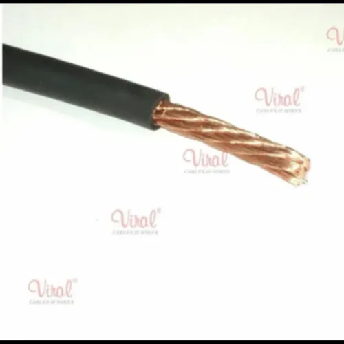
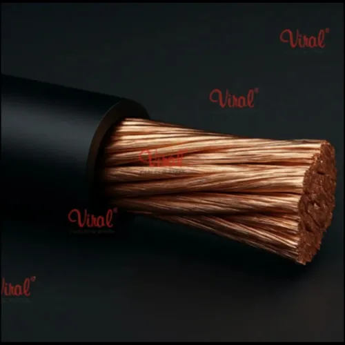
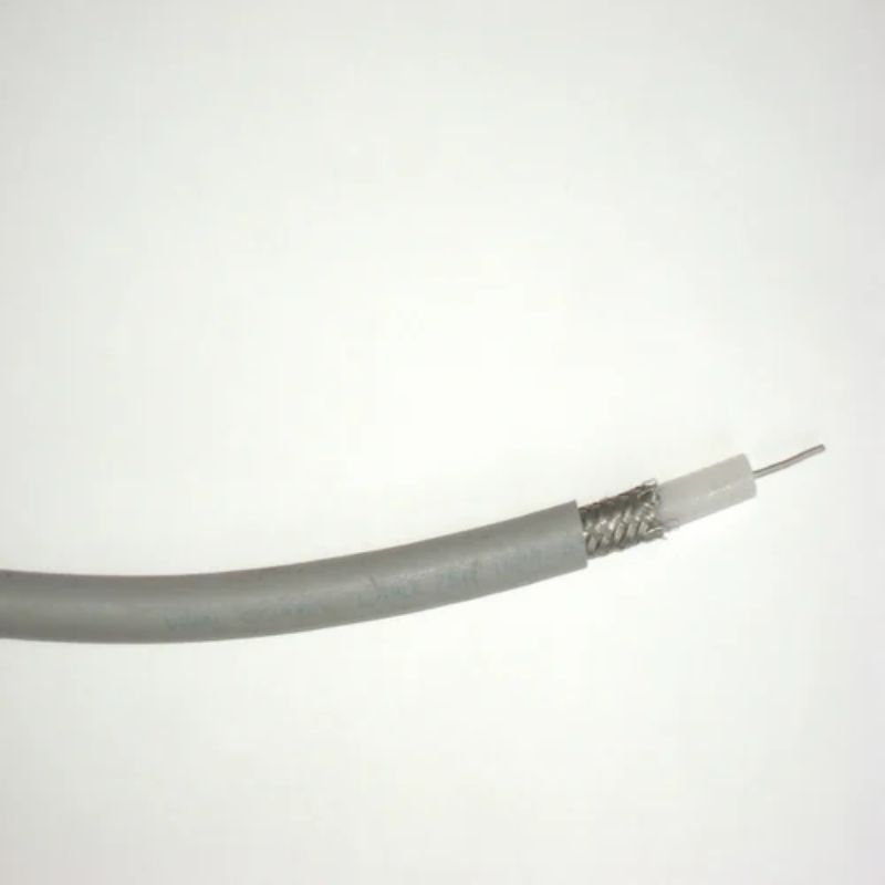 | HV Cables 2 Core Aircraft Ignition High Voltage Cables Number of Cores 2 Core Conductor Material Copper Min Voltage 2 kV Max Voltage 100 kV Type High Voltage Insulation Material PVC Aircraft Ignition... View product → |
 | HV Cables 1 Core Copper High Voltage Cables Number of Cores 1 Core Conductor Material Copper Insulation Material PVC Min Voltage 2 kV Max Voltage 100 kV Type High Voltage We at viral... View product → |
Frequently asked questions
What should you confirm before troubleshooting a two-core aircraft ignition cable?
Confirm the ignition configuration, identify what “two core” describes, and record the observed symptom, such as misfire, hard starting or intermittent ignition.
What should you inspect before testing an aircraft ignition cable?
Inspect the cable jacket, terminals, seals, connectors, bend points, routing, clamps and nearby heat or vibration damage before connecting test equipment.
How do you test a two-core aircraft ignition high-voltage cable?
Test each high-voltage core, the shield and insulation separately, using equipment and procedures approved for the aircraft ignition system.
How do you isolate an aircraft ignition cable failure?
Compare the test results for each core and the shield, then determine whether the fault is in the cable, terminal, connector, insulation or another ignition component.